
Getting USB up and running in bare-metal mode using the ST HAL drivers on my custom STM32MP135 board took a couple attempts. After a few false starts with the example projects, I was able to make the board enumerate correctly, handle data transfers, and even read and write files reliably. In this article, I’ll walk through the hardware tweaks, HAL configuration, and debugging steps that helped me turn a stubborn USB interface into a fully working USB Mass Storage device.
I gave up trying to make the provided CDC_Standalone example from
STM32Cube_FW_MP13_V1.2.0
to work on the eval board, let alone the custom board. Instead, let’s get USB to
work step by step.
First, the VDD3V3_USBHS must not be powered on when VDDA1V8_REG is not
present. For that, we have the switch U201 (NCP380), but the board unfortunately
uses the adjustable-current version of the switch w/o the adjustment resistor
present, so the USBHS circuitry is disabled. So we first have to solder a
resistor (I had 39k + 10k at hand) to enable power to the USB circuit.
With that fix, if I reset the device with BOOT=000 (so PA13 LED blinks), then
plug the USB cable, then the LED stops blinking and the device manager shows
DFU in FS Mode @Device ID /0x501, @Revision ID /0x1003 as it should—so the
hardware works, we just need to fix the code. (Without the added resistor,
Windows was not able to enumerate the device and the Device Manager shows it as
Unknown USB Device (Device Descriptor Request Failed).)
In the main() function, I blink LED and print “:” on UART4 every second after
starting the USB using MX_USB_OTG_HS_PCD_Init() and HAL_PCD_Start();
functions. If I load the code with the USB cable plugged in, the “:” signs get
printed every second as they should, and also the LED blinks. If I unplug the
USB cable, then the printing and blinking stops—the code appears locked up.
The code also locks up if I select “Disable device” in Windows Device Manager.
If I load the code with USB cable not plugged in, only the first “:” gets
printed and then the code locks up.
Before the main loop we also see that OTG_GCCFG: 0x00000000, which means that
both of the following are disabled:
Note that the hardware has a permanent 1.5K pullup (up to +3.3V) on D+, so the
USB driver does not need VBUS sensing. (The board is externally powered, so
removing the cable would not unpower the core or the USB PHY.) We explicitly
disable sensing VBUS in MX_USB_OTG_HS_PCD_Init(), where we create the
structure passed to HAL_PCD_Init() with the following line:
hpcd_USB_OTG_HS.Init.vbus_sensing_enable = DISABLE;
With that request, the driver function USB_DevInit() clears the enable for
VBUS sensing in the GCCFG register:
if (cfg.vbus_sensing_enable == 0U)
{
USBx_DEVICE->DCTL |= USB_OTG_DCTL_SDIS;

/* Deactivate VBUS Sensing B */
USBx->GCCFG &= ~USB_OTG_GCCFG_VBDEN;

/* B-peripheral session valid override enable */
USBx->GOTGCTL |= USB_OTG_GOTGCTL_BVALOEN;
USBx->GOTGCTL |= USB_OTG_GOTGCTL_BVALOVAL;
}
I checked that the USB interrupt service routine (HAL_PCD_IRQHandler()) is
linked by locating it in the map file (and not in the “Discarded input
sections”!). Just before the main loop, we print OTG_GAHBCFG: 0x00000001,
showing that OTG USB interrupts are unmasked, and OTG_GINTMSK: 0x803C3810,
which means the following interrupts are enabled:
If we IRQ_Disable(OTG_IRQn) before the main loop, than “Disable device” and
“Enable device” do not cause the core lockup. So, we just need to find out which
of the OTG USB interrupts exactly are not correctly handled, one by one.
If we enable just USBSUSPM, the locked happens. If we allow all the interrupts
that HAL enables, and then disable USBSUSPM, the lockup does not happen.
If we enable USBRST only, lockup does not happen. If we in addition add
ENUMDNEM, still no lockup. Add IEPINT, no lockup. Add OEPINT, no lockup.
Add IISOIXFRM, PXFRM_IISOOXFRM, and WUIM: no lockup.
If USBRST is the only enabled OTG interrupt, then the code locks up if the
cable is not plugged in when it starts executing, but it does not lock up if the
cable is present when it starts executing and is then unplugged.
If USBSUSPM is the only enabled OTG interrupt, then the code locks up both if
the cable is not present initially, or if it is unplugged later.
Meanwhile I figured out how to get the JTAG to work mostly reliably. First,
remember to boot with BOOT=100, the “Engineering debug mode”, otherwise the
JTAG is disabled. Then, the procedure is
JLinkGDBServer.exearm-none-eabi-gdb -q -x load.gdbThe load.gdb file is as follows:
set confirm off
set pagination off
file build/main.elf
target remote localhost:2330
monitor reset
monitor flash device=STM32MP135F
load build/main.elf
monitor go
break main
step
Loaded with the debugger, the program runs as before, and once USB “Disable device” is clicked from the Windows Device Manager, the following appears on the debugger after pressing Ctrl-C:
Program received signal SIGTRAP, Trace/breakpoint trap.
0x2ffe0104 in Vectors () at drivers/startup_stm32mp135fxx_ca7.c:444
444       __asm__ volatile(
(gdb) bt
#0  0x2ffe0104 in Vectors () at drivers/startup_stm32mp135fxx_ca7.c:444
Backtrace stopped: previous frame identical to this frame (corrupt stack?)
(gdb)
Searching the forums, I found a
post
where user bsvi discovered that startup_stm32mp135fxx_ca7.c take interrupts to
thumb mode in the Reset_Handler():
/* Set TE bit to take exceptions in Thumb mode */
"ORR R0, R0, #(0x1 << 30) \n"
If the vector table is aligned and encoded as ARM mode, the of course it cannot
work. Adding -mthumb and the interrupt immediately fired as was able to
confirm via a flashing LED at the top of the HAL_PCD_IRQHandler(). Stopping
the debugger there (Ctrl-C) confirmed that the code was executing there.
Better yet, we can remove the -mthumb and simply take interrupts to ARM mode:
/* TE = 0, exceptions enter ARM mode */
"BIC R0, R0, #(1 << 30) \n"
I changed the debug code at the top of HAL_PCD_IRQHandler() to just a print
statement, and it prints any time the USB cable is plugged in and out. Great!
Now that USB interrupts are no longer freezing the whole system, we can begin work on integrating the ST USB Device “middleware”. The initialization proceeds as the following approximate sequence of function calls:
MX_USB_Device_Init (usb_device.c)
   USBD_Init (usbd_core.c)
      USBD_LL_Init (usb_conf.c)
         HAL_PCD_Init (usbd_conf.c)
         HAL_PCDEx_SetRxFiFo (stm32mp13xx_hal_pcd_ex.c)
         HAL_PCDEx_SetTxFiFo (stm32mp13xx_hal_pcd_ex.c)
   USBD_RegisterClass (usbd_core.c)
   USBD_CDC_RegisterInterface (usbd_cdc.c)
   USBD_Start (usbd_core.c)
      USBD_LL_Start (usbd_conf.c)
         HAL_PCD_Start (stm32mp13xx_hal_pcd.c)
            USB_DevConnect (stm32mp13xx_ll_usb.c)
         USBD_Get_USB_Status (usbd_conf.c)
The example above is for a CDC-class application, but here we’re interested in a mass-storage class device (MSC). The USB files divide into four types:
stm32mp13xx_ll_usb.c, stm32mp13xx_hal_pcd.c,
stm32mp13xx_hal_pcd_ex.cusbd_core.c, usbd_ctlreq.h, usbd_ioreq.cusbd_msc.c, usbd_msc_bot.c, usbd_msc_data.c,
usbd_msc_scsi.cusb_device.c, usbd_conf.c, usbd_desc.c, usbd_msc_storage.cAn example of how the ST drivers are used for MSC class is provided in this repository.
For testing, we call the following from the main function:
USBD_Init(&USBD_Device, &MSC_Desc, 0);
USBD_RegisterClass(&USBD_Device, USBD_MSC_CLASS);
USBD_MSC_RegisterStorage(&USBD_Device, &USBD_MSC_fops);
USBD_Start(&USBD_Device);
The functions complete, and then the main loop is active, blinking LED and
printing to UART. The debug print in HAL_PCD_IRQHandler shows that the IRQ is
called a couple times, but after a few seconds, the Windows Device Manager shows
Unknown USB Device (Device Descriptor Request Failed).
As it turns out, I have forgotten to add the callbacks into usbd_conf.c. Once
that was done, the USB access from the Windows computer caused an immediate Data
Abort on the STM32MP135.
The aborts happen in usbd_msc_scsi.c in lines such as the following:
hmsc->scsi_blk_addr =
    ((uint32_t)params[2] << 24) |
    ((uint32_t)params[3] << 16) |
    ((uint32_t)params[4] << 8) |
    (uint32_t)params[5];

hmsc->scsi_blk_len =
    ((uint32_t)params[7] << 8) |
    (uint32_t)params[8];
As it happens, with some optimizations (I’m using -Os to make the whole
program fit in SYSRAM!) the compiler optimizes the byte access into a misaligned
32-bit access. Forcing a volatile cast fixes the problem, as follows:
hmsc->scsi_blk_addr =
    (((uint32_t)((volatile uint8_t*)params)[2]) << 24) |
    (((uint32_t)((volatile uint8_t*)params)[3]) << 16) |
    (((uint32_t)((volatile uint8_t*)params)[4]) <<  8) |
    ((uint32_t)((volatile uint8_t*)params)[5]);

hmsc->scsi_blk_len =
    (((uint32_t)((volatile uint8_t*)params)[7]) <<  8) |
    ((uint32_t)((volatile uint8_t*)params)[8]);
Make sure to repeat this several times! Search for scsi_blk_addr in
usbd_msc_scsi.c until you’ve cast all of them correctly.
Then, at last, the USB device enumerates as MSC correctly, and we can even read and write raw data! However, Windows is not able to format the device.
Now that data can be read and written to, we observe an odd pattern:
WRITE: eb 3c 90 6d 6b 66 73 2e 66 61
READ:  eb 00 90 3c 6b 6d 73 66 66 2e
Every other byte is a bit wrong, or reshuffled. Sounds familiar? Yes, it happens if DDR writes are not aligned to word boundaries, as we experienced before with the SD card, copying it’s data to DDR. (Somehow reads are not affected by this? ChatGPT says that AXI supports unaligned / byte reads natively, but not writes.)
With the write fixed (i.e., done in correctly aligned units of 4 bytes), the device format works, and we can even copy files to the mass storage device, and read them back. The problems is now … read and write speeds are about 700 kB/s.
As it happens, the USB interface on the custom board has a external, physical 1.5K pullup on the D+ line which signals a Full-Speed device. To switch to High-Speed mode, the device needs to be able to have the pullup present initially, but then switch it off. Indeed, Device Manager shows that the device enumerated as a Full-Speed device, hence the low data rates.
Removing the resistor, the device does not enumerate, or appear at all in the Device Manager. However, we can simply set
hpcd_USB_OTG_HS.Init.speed = PCD_SPEED_FULL;
in USBD_LL_Init() function (usbd_conf.c), and then everything works as
before. So something must be wrong with the high-speed mode configuration.
Since removing the 1.5K pullup which was keeping the device in Full-Speed (FS)
mode, the device does not enumerate, neither in DFU mode (with BOOT pins set
to 000), nor using my test firmware (unless I request FS mode directly).
Inserting print statements or debug breakpoints in USB interrupt handler we see
that the USB reset is detected, the device is correctly switched to HS mode
(speed=0), the Rx/Tx FIFOs are large enough, the RXFLVL interrupt is enabled
but it never arrives. The enumeration completes, but the device does not see any
setup or data packets enter the FIFO, and then the device gets suspended,
presumably because it did not reply to the host’s communications. The device
never appears in the Device Manager, or even in USB Device Tree
Viewer.
With BOOT=000, pressing reset causes the PA13 LED to blink, and when the USB
cable is attached, the blinking stops. But looking at the device and USB trees,
nothing happens. Even the STM32_Programmer_CLI -l usb does not see anything:
      -------------------------------------------------------------------
                       STM32CubeProgrammer v2.18.0
      -------------------------------------------------------------------

=====  DFU Interface   =====

No STM32 device in DFU mode connecte
Now a different USB cable was found, connected to a different hub/port. Again
BOOT=000, press reset, PA13 LED blinks, and the new cable is connected, and
the blinking stops. Immediately the Device Manager and the USB Device Tree
Viewer report DFU in FS Mode @Device ID /0x501, @Revision ID /0x1003, so the
device enumerated. (About the “FS”: I think that’s just a cached name, since the
USB Tree also says that “Device Connection Speed : High-Speed”.) And CubeProg:
      -------------------------------------------------------------------
                       STM32CubeProgrammer v2.18.0
      -------------------------------------------------------------------

=====  DFU Interface   =====

Total number of available STM32 device in DFU mode: 1

  Device Index           : USB1
  USB Bus Number         : 001
  USB Address Number     : 005
  Product ID             : DFU in HS Mode @Device ID /0x501, @Revision ID /0x1003
  Serial number          : 001E00263133511332303636
  Firmware version       : 0x0110
  Device ID              : 0x0501
Clearly, the bad cable or hub or port was stopping the HS enumeration, at least
in DFU mode. Now let’s switch to BOOT=100, reset, and load our firmware via
JTAG. And … it enumerates immediately! Windows offers to format it as FAT32,
and the file write speed is up to about 4 MB/s, and read about 2 MB/s. Great
success! But could have checked the cable first.
Regarding the low-ish data rates: it’s probably limited by a combination of the
slow implementations of the usbd_msc_storage.c backend, and the HAL driver or
other things. For firmware flashing the speed is good enough. More importantly,
it proves that everything is now wired correctly. Nonetheless, let’s see if we
can make it go faster than the 2–4 MB/s.
Changing the compiler optimization level from -Os to -O3 brings the write
speed up to 7.6 MB/s. Windows has a built-in disk performance checker which
shows:
C:\Users\Jkastelic> winsat disk -drive e
> Disk  Random 16.0 Read                       2.87 MB/s          4.5
> Disk  Sequential 64.0 Read                   2.91 MB/s          2.2
> Disk  Sequential 64.0 Write                  7.67 MB/s          2.6
> Average Read Time with Sequential Writes     8.566 ms          4.9
> Latency: 95th Percentile                     21.499 ms          4.5
> Latency: Maximum                             22.485 ms          7.9
> Average Read Time with Random Writes         9.149 ms          4.7

winsat disk -write -ran -drive e
> Disk  Random 16.0 Write                      7.46 MB/s
Next, re-write the STORAGE_Read function to use 32-bit writes instead of
forcing 8-bit accesses (as we did previously while debugging the data
corruption). This improves the reads significantly:
> Disk  Random 16.0 Read                       9.02 MB/s          5.3
> Disk  Sequential 64.0 Read                   9.39 MB/s          2.8
> Disk  Sequential 64.0 Write                  7.71 MB/s          2.6
> Average Read Time with Sequential Writes     3.134 ms          6.6
> Latency: 95th Percentile                     8.109 ms          5.9
> Latency: Maximum                             9.516 ms          8.0
> Average Read Time with Random Writes         3.138 ms          6.5
Now consider the FIFO allocation. The USB OTG core in the STM32MP135 has 4 kB of total FIFO. If we used all of it just for sending data back to the host, at the 480 MBit/s (70 MB/s) data rate, the microcontroller would fire interrupts or DMA requests every 67 μs. (USB devices designed for mass data transfer probably have larger buffers.) Currently we have
HAL_PCDEx_SetRxFiFo(&hpcd, 0x200);
HAL_PCDEx_SetTxFiFo(&hpcd, 0, 0x40);
HAL_PCDEx_SetTxFiFo(&hpcd, 1, 0x100);
Let us significantly increase the buffer that sends data to the host:
HAL_PCDEx_SetRxFiFo(&hpcd, 0x100);
HAL_PCDEx_SetTxFiFo(&hpcd, 0, 0x20);
HAL_PCDEx_SetTxFiFo(&hpcd, 1, 0x2e0);
Unfortunately, the read/write performance is essentially unchanged:
> Disk  Random 16.0 Read                       9.89 MB/s          5.4
> Disk  Sequential 64.0 Read                   10.28 MB/s          2.9
> Disk  Sequential 64.0 Write                  7.59 MB/s          2.6
> Average Read Time with Sequential Writes     3.311 ms          6.5
> Latency: 95th Percentile                     8.236 ms          5.9
> Latency: Maximum                             9.306 ms          8.1
> Average Read Time with Random Writes         3.279 ms          6.5
All of that was without DMA. It might be that DMA would make it faster, or at least unburden the CPU—but in this example, the CPU is not doing anything except copying the data. (CPU can actually be faster in copying; the point of DMA is to allow the CPU to do other, more interesting things while the copy is taking place.)
You can find the final version of the USB test in this repository.
It compiles to about 117 kB with -Os optimization, so it fits in
SYSRAM directly. If you need more speed, -O3 makes it compile to about 136 kB.
That’s still acceptable if we combine all of the on-chip memory into a single
block, as shown in this excerpt from the linker
script:
MEMORY {
      SYSRAM_BASE (rwx)   : ORIGIN = 0x2FFE0000, LENGTH = 128K
      SRAM1_BASE (rwx)    : ORIGIN = 0x30000000, LENGTH = 16K
      SRAM2_BASE (rwx)    : ORIGIN = 0x30004000, LENGTH = 8K
      SRAM3_BASE (rwx)    : ORIGIN = 0x30006000, LENGTH = 8K
      /* InternalMEM = SYSRAM + SRAM1 + SRAM2 + SRAM3 */
      InternalMEM (rwx)   : ORIGIN = 0x2FFE0000, LENGTH = 160K
      DDR_BASE (rwx)      : ORIGIN = 0xC0000000, LENGTH = 512M
}

Limitation is the only way to get anything done. The less one aims to do, the more gets done. By the time the aim becomes to do nothing at all, everything is accomplished.
On a practical level, trying to do too many things at once results in not having enough time for any single one of them. Thus the paradox: the less one is trying to do, the more gets done. At any rate, it’s impossible to do more than one thing at a time. The closer one approaches to the ideal of unity, the more efficient the work becomes. Distraction is dissipation; limitation is focus.
This is not a moral statement but a practical one: limitations free your energy for what matters.

This article is also available as a Jupyter notebook.
Previously we have explored how to flash the STM32MP135 using the STM32CubeProg over USB and remained puzzled why we need 1.5G of code just to transfer some serial data. Here, we will flash the chip by talking to the built-in ROM bootloader over UART with a couple lines of Python, as explained in an ST app note[1]. The article is in three sections: (1) define the communication functions, (2) use them on the evaluation board, (3) use them on a custom board.
This section documents how the STM32MP1 ROM bootloader communicates over UART, including the supported commands, packet formats, checksum rules, and Python helper functions used to implement the protocol. Skip to the next section to see how these functions are used.
The supported commands are listed below:
def interp_cmd(b):
    if b == 0x00:
        return "Get"
    elif b == 0x01:
        return "Get Version"
    elif b == 0x02:
        return "Get ID"
    elif b == 0x03:
        return "Get phase"
    elif b == 0x11:
        return "Read Memory"
    elif b == 0x12:
        return "Read Partition"
    elif b == 0x21:
        return "Start (Go)"
    elif b == 0x31:
        return "Download (Write Memory)"
    else:
        return "???"
All communications from STM32CubeProgrammer (PC) to the device are verified as follows:
The UART/USART even parity is checked.
For each command the host sends a byte and its complement (XOR = 0x00).
The device performs a checksum on the sent/received datablocks. A byte containing the computed XOR of all previous bytes is appended at the end of each communication (checksum byte). By XORing all received bytes, data + checksum, the result at the end of the packet must be 0x00. A timeout must be managed in any waiting loop to avoid any blocking situation.
def pack_cmd(cmd):
    if cmd not in [0x00, 0x01, 0x02, 0x03, 0x11, 0x12, 0x21, 0x31]:
        raise RuntimeError("Invalid cmd requested.")
    # command followed by its complement
    return struct.pack("BB", cmd, 0xff-cmd)
Each command packet is either accepted (ACK answer), discarded (NACK answer) or aborted (unrecoverable error):
def interp_byte(b):
    if b == 0x79:
        return "ACK"
    elif b == 0x1F:
        return "NACK"
    elif b == 0x5F:
        return "ABORT"
    else:
        return format(b, '#04x')

def get_ack(note=""):
    r = mp1.read_bytes(1)[0]
    print(f"{format(r, '#04x')}\t\t{interp_byte(r)}{note}")
    if interp_byte(r) != "ACK":
        raise RuntimeError("Did not receive ACK.")
Once the serial boot mode is entered (boot pins set to 000), all the UART/USART
instances are scanned by the ROM code, monitoring for each instance the
USARTx_RX line pin, waiting to receive the 0x7F data frame (one start bit,
0x7F data bits, none parity bit and one stop bit).
def uart_init():
    mp1.write_raw(struct.pack("B", 0x7F))
    get_ack(note="")
The Get command returns the bootloader version and the supported commands. When the device receives the Get command, it transmits the version and the supported command codes to the host. The commands not supported are removed from the list.
def get():
    # Get command
    mp1.write_raw(pack_cmd(0x00))

    # Response: ACK
    get_ack()

    # Response: number of following bytes – 1
    num_bytes = mp1.read_bytes(1)[0]
    if num_bytes >= 0:
        print(f"{format(num_bytes, '#04x')}\t\t{num_bytes} + 1 bytes to follow")
    else:
        print(f"{format(num_bytes, '#04x')}")
        raise RuntimeError("Did not receive number of bytes to follow.")

    # Response: Bootloader version
    r = mp1.read_bytes(1)[0]
    print(f"{format(r, '#04x')}\t\tversion {int(hex(0x10)[2:])/10}")

    # Response: device ID
    for i in range(num_bytes):
        r = mp1.read_bytes(1)[0]
        print(f"{format(num_bytes, '#04x')}\t\tcmd = {interp_cmd(r)}")

    # Response: ACK
    get_ack()
The Get version command is used to get the version of the running component. When the device receives the command, it transmits the version to the host.
def get_version():
    # Get version command
    mp1.write_raw(pack_cmd(0x01))

    # Response: ACK
    get_ack()

    # Response: Bootloader version
    r = mp1.read_bytes(1)[0]
    print(f"{format(r, '#04x')}\t\tversion {int(hex(0x10)[2:])/10}")

    # Response: Option byte 1
    r = mp1.read_bytes(1)[0]
    print(f"{format(r, '#04x')}\t\tOption byte 1")

    # Response: Option byte 2
    r = mp1.read_bytes(1)[0]
    print(f"{format(r, '#04x')}\t\tOption byte 2")

    # Response: ACK
    get_ack()
The Get ID command is used to get the version of the device ID (identification). When the device receives the command, it transmits the device ID to the host.
def get_id():
    # Get ID command
    mp1.write_raw(pack_cmd(0x02))

    # Response: ACK
    get_ack()

    # Response: number of following bytes – 1
    r = mp1.read_bytes(1)[0]
    if r >= 0:
        print(f"{format(r, '#04x')}\t\t{r} + 1 bytes to follow")
    else:
        print(f"{format(r, '#04x')}")
        raise RuntimeError("Did not receive number of bytes to follow.")

    # Response: device ID
    r = mp1.read_bytes(2)
    if r == b'\x05\x00':
        print(format(r[0], '#04x'), format(r[1], '#04x'), "\tSTM32MP15x")
    elif r == b'\x05\x01':
        print(format(r[0], '#04x'), format(r[1], '#04x'), "\tSTM32MP13x")
    else:
        print(format(r[0], '#04x'), format(r[1], '#04x'))
        raise RuntimeError("Did not receive device ID.")

    # Response: ACK
    get_ack()
The Get phase command enables the host to get the phase ID, in order to identify the next partition that is going to be downloaded.
The download address, when present, provides the destination address in memory. A value of 0xFFFFFFFF means than the partition is going to be written in NVM.
Phase ID = 0xFF corresponds to an answered value Reset, in this case the information bytes provide the cause of the error in a string just before executing the reset.
The ROM code sends phase = TF-A
Byte 1: ACK
Byte 2 N = 6
Byte 3: phase ID (file containing FSBL = TF-A, 1)
Byte 4-7: 0x2FFC2400 on STM32MP15x, 0x2FFDFE00 on STM32MP13x
Byte 8: X = 1
Byte 9: 0: reserved
Byte 10: ACK
def get_phase():
    # Get phase command
    mp1.write_raw(pack_cmd(0x03))

    # Response: ACK
    get_ack()

    # Response: number of following bytes – 1
    r = mp1.read_bytes(1)[0]
    if r >= 0:
        print(f"{format(r, '#04x')}\t\t{r} + 1 bytes to follow")
    else:
        print(f"{format(r, '#04x')}")
        raise RuntimeError("Did not receive number of bytes to follow.")

    # Response: phase ID
    r = mp1.read_bytes(1)[0]
    print(f"{format(r, '#04x')}\t\tPhase ID")

    # Response: download address
    r = mp1.read_bytes(4)
    print(format(r[3], '#04x'), end='')
    print(format(r[2], '02x'), end='')
    print(format(r[1], '02x'), end='')
    print(format(r[0], '02x'), end='')
    print("\tDownload address")

    # Response: number of additional bytes
    r = mp1.read_bytes(1)[0]
    print(f"{format(r, '#04x')}\t\t{r} additional bytes following")

    # Response: reserved
    r = mp1.read_bytes(1)[0]
    print(f"{format(r, '#04x')}\t\t{r} Reserved")

    # Response: ACK
    get_ack()
The download command is used to download a binary code (image) into the SRAM memory or to write a partition in NVM.
Two types of operations are available:
Normal operation: download current partition binary to the device. For initialization phase the partitions are loaded in SRAM, otherwise for writing phase the partition are written in NVM.
Special operation: download non-signed data to non-executable memory space
A Start command is necessary to finalize these operations after the download command.
The Packet number is used to specify the type of operation and the number of the current packet. The table below gives the description of the packet number.
| Byte | Value | Description |
|---|---|---|
| 3 | 0x00 | Normal operation: write in current phase |
| . | 0xF2 | Special operation: OTP write |
| . | 0xF3 | Special operation: Reserved |
| . | 0xF4 | Special operation PMIC: NVM write |
| . | Others | Reserved |
| 0-2 | — | Packet number, increasing from 0 to 0xFFFFFF (*) |
Packet number it is not an address as on STM32 MCU with only memory mapped flash, but the index of the received packet. The offset of the packet N the offset in the current partition/phase is N* 256 bytes when only full packets are used.
def download(num, data):
    # Data sanity check
    print(f"Packet number {num} of length {len(data)}:")
    if len(data) > 256:
        raise RuntimeError("Too much data to send.")

    # Send "Download" command
    mp1.write_raw(pack_cmd(0x31))

    # Response: ACK
    get_ack(" command")

    # Packet number
    i0 = (num >> 0*8) & 0xff
    i1 = (num >> 1*8) & 0xff
    i2 = (num >> 2*8) & 0xff
    mp1.write_raw(struct.pack("BBBB", 0x00, i2, i1, i0))

    # Checksum byte: XOR (byte 3 to byte 6)
    mp1.write_raw(struct.pack("B", i2 ^ i1 ^ i0))

    # Response: ACK
    get_ack(" packet number")

    # Packet size (0 < N < 255)
    mp1.write_raw(struct.pack("B", len(data) - 1))

    # N-1 data bytes
    for d in data:
        mp1.write_raw(struct.pack("B", d))

    # Checksum byte: XOR (byte 8 to Last-1)
    checksum = len(data) - 1
    for d in data:
        checksum ^= d
    mp1.write_raw(struct.pack("B", checksum))

    # Response: ACK
    get_ack(" data")
The Read memory command is used to read data from any valid memory address in the system memory.
When the device receives the read memory command, it transmits the ACK byte to the application. After the transmission of the ACK byte, the device waits for an address (4 bytes) and a checksum byte, then it checks the received address. If the address is valid and the checksum is correct, the device transmits an ACK byte, otherwise it transmits a NACK byte and aborts the command.
When the address is valid and the checksum is correct, the device waits for N (N = number of bytes to be received -1) and for its complemented byte (checksum). If the checksum is correct the device transmits the needed data (N+1 bytes) to the application, starting from the received address. If the checksum is not correct, it sends a NACK before aborting the command.
def read_memory(addr, num_bytes):
    print("Note: read memory command not supported by ROM code STM32MP13x.")

    # Data sanity check
    if num_bytes > 256:
        raise RuntimeError("Too much data to receive.")

    # Send "Read memory" command
    mp1.write_raw(pack_cmd(0x11))

    # Response: ACK
    get_ack(" command")

    # Start address
    i0 = (addr >> 0*8) & 0xff
    i1 = (addr >> 1*8) & 0xff
    i2 = (addr >> 2*8) & 0xff
    mp1.write_raw(struct.pack("BBBB", 0x00, i2, i1, i0))

    # Checksum byte: XOR (byte 3 to byte 6)
    mp1.write_raw(struct.pack("B", i2 ^ i1 ^ i0))

    # Response: ACK
    get_ack(" start address")

    # Number of bytes to be received – 1 (N = [0, 255])
    # (also Checksum byte: XOR)
    mp1.write_raw(pack_cmd(num_bytes - 1))

    # Response: ACK
    get_ack(" number of bytes")
The Start command is used:
To execute the code just downloaded in the memory or any other code by branching to an address specified by the application. When the device receives the Start command, it transmits the ACK byte to the application. If the address is valid the device transmits an ACK byte and jumps to this address, otherwise it transmits a NACK byte and aborts the command.
To finalize the last download command, when the host indicates the address = 0xFFFFFFFF.
def start(addr):
    # Send "Start" command
    mp1.write_raw(pack_cmd(0x21))

    # Response: ACK
    get_ack(" command")

    # Start address
    i0 = (addr >> 0*8) & 0xff
    i1 = (addr >> 1*8) & 0xff
    i2 = (addr >> 2*8) & 0xff
    i3 = (addr >> 3*8) & 0xff
    mp1.write_raw(struct.pack("BBBB", i3, i2, i1, i0))

    # Checksum byte: XOR (byte 3 to byte 6)
    mp1.write_raw(struct.pack("B", i3 ^ i2 ^ i1 ^ i0))

    # Response: ACK
    get_ack(" address")
To download a complete file:
def down_file(fname='tf-a-stm32mp135f-dk.stm32'):
    # size of each chunk (must be <= 256 bytes)
    sz = 256

    # open file with the bitstream
    with open(fname, 'rb') as f:
        fb = f.read()

    # split file into this many chunks
    num_chunks = int(np.ceil(len(fb) / sz))

    # send each chunk one by one
    for i in tqdm(range(num_chunks)):
        chunk = fb[i*sz : (i+1)*sz]
        download(i, chunk)

    # necessary to finalize download
    start(0xFFFFFFFF)
We simply run the functions one after the other and verify that the output printed matches what’s shown here.
As an example, we will use the Blink program that we develop, compile, and package in this repo.
>>> uart_init()
0x79		ACK

>>> get()
0x79		ACK
0x06		6 + 1 bytes to follow
0x40		version 1.0
0x06		cmd = Get
0x06		cmd = Get Version
0x06		cmd = Get ID
0x06		cmd = Get phase
0x06		cmd = Start (Go)
0x06		cmd = Download (Write Memory)
0x79		ACK

>>> get_version()
0x79		ACK
0x10		version 1.0
0x00		Option byte 1
0x00		Option byte 2
0x79		ACK

>>> get_id()
0x79		ACK
0x01		1 + 1 bytes to follow
0x05 0x01 	STM32MP13x
0x79		ACK

>>> get_phase()
0x79		ACK
0x06		6 + 1 bytes to follow
0x01		Phase ID
0x2ffdfe00	Download address
0x01		1 additional bytes following
0x00		0 Reserved
0x79		ACK

>>> down_file(fname='blink.stm32')
Packet number 0 of length 256:
0x79		ACK command
0x79		ACK packet number
0x79		ACK data
...
(skip over lots of packets)
...
Packet number 264 of length 156:
0x79		ACK command
0x79		ACK packet number
0x79		ACK data
0x79		ACK command
0x79		ACK address
After a little bit, the red LED on the evaluation board will blink. Success!
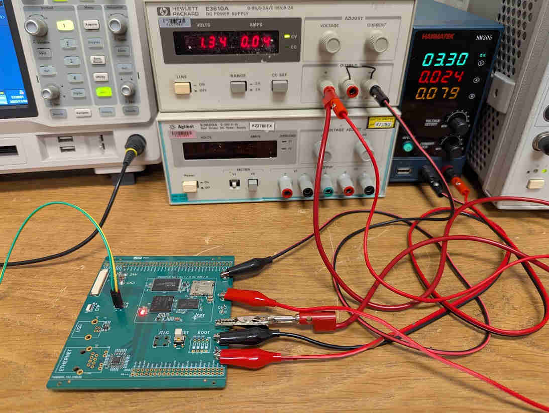
Amazingly, the exact same procedure works on any custom board, so long as it breaks out the UART4 pin and applies 3.3V and 1.35V power supplies in the correct sequence. Find the schematics and layout files for my board in this repository.
Since the custom board does not use STPMIC1, the code for the blink example is even simpler. Find it here.
The UART wires (green/yellow) and the two power supplies is all that needs to be connected, and then the red LED (middle of the PCB) will blink. Yes, the setup is that simple!
ST application note AN5275, “USB DFU/USART protocols used in STM32MP1 Series bootloaders”. ↩︎